


Recently, we explained that plans were afoot for a substantial electrical upgrade on Penny. We added a simple 12V accessory socket at that stage to make phone charging easier, but in doing so, found plenty of things that looked like they were ready to be retired.
Some of this was older, well-meaning DIY, some of it was just tired and old, but all of it needed to be improved if we wanted Penny to cope away from hook-ups at music festivals, field campsites and anywhere else we might fancy pitching up on our travels.
Terminal ailment
We aren’t sure exactly how far we are going to go with this just yet, but a quick scan of Penny’s battery and 12V set-up showed that we definitely needed to get the foundations right before we started spending money on upgrades that might be tripped up by basic shortcomings.
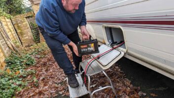
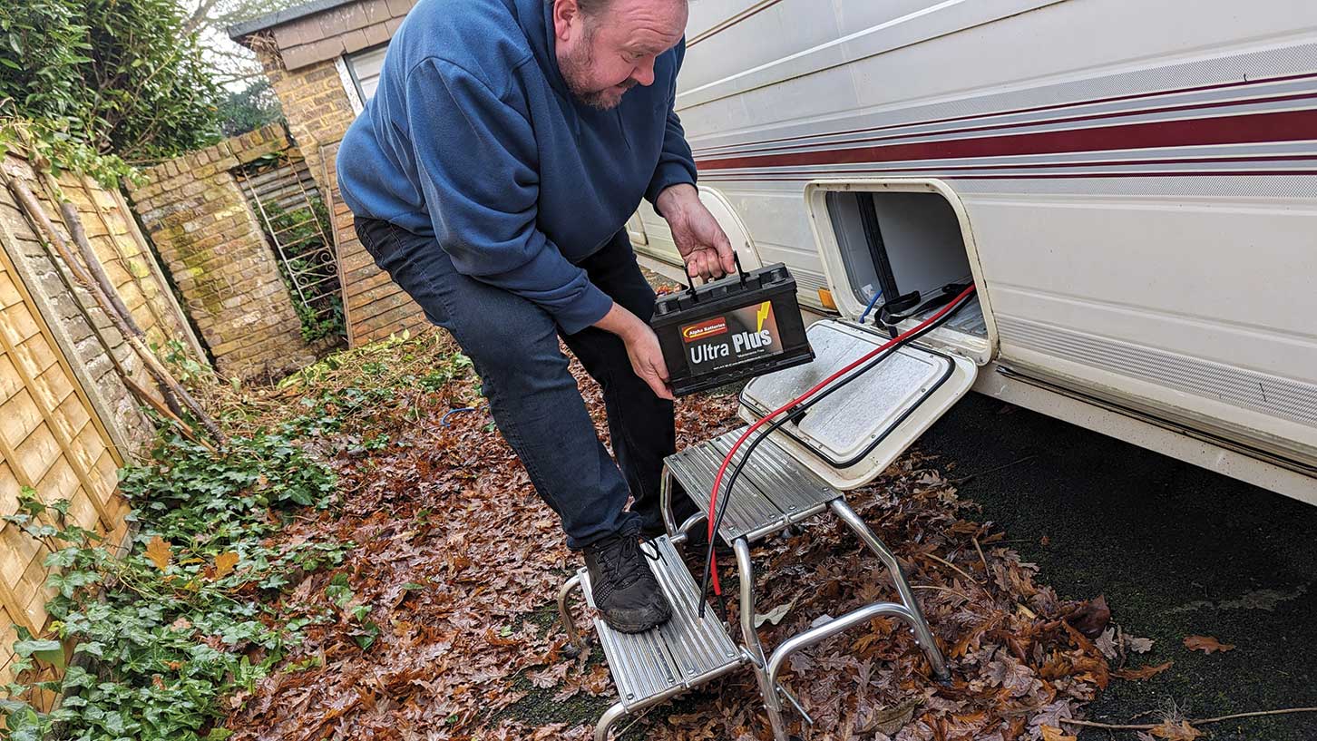
The first problem was a dead easy one to put right. When we first bought Penny, she didn’t have a leisure battery – but we did, from our old campervan. If you’re in need of one for your tourer, check out our guide to the best caravan leisure battery guide to see our favourite picks.

It was not new, but it had been stored on a trickle charger and it fitted the caravan battery box. This was a fairly typical unbranded 80Ah leisure battery, so I set about putting it to use.
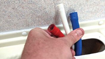
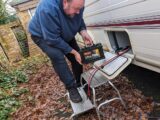
The battery box is one of the fully integrated types commonly found in 1990s caravans, which incorporates the mains socket input. It cleaned up well, the door and latch all worked fine and the seal was intact. The cables running to the battery, however, were a bit of a mess.
A couple of nasty kinks in the cables, insulation that had shrunk badly and ratty-looking terminals did not inspire much confidence. There was also the remains of a cable fitted with old crocodile clips, which I think might have been used to power an awning light. Nasty.

Adaptable additions
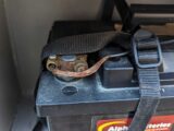
My first purchase was a pair of terminals from Auto Electrical Supplies. I opted for some neat multi-stud ones, which make it easier to add extra battery connections if required.
The terminals were a fraction under £5 each, with an extra £2 for safety cover for the positive terminal. Money well spent.
I snipped the old terminals off, rather than wrestling with the crusty screws. I stripped the cables back until they had intact insulation and crimped on a couple of ring terminals. This was an improvement, but I wasn’t exactly thrilled with it. The only way of getting power in and out of a battery is with the cables attached to it. If they are damaged or too thin, you have immediate safety and performance concerns.
Ours were a little damaged, but too thin for future upgrade. The battery box is quite tight for space and we want to add some accessories. That would mean running additional cables, and that means hassle. I put everything back with the new terminals, but started planning an immediate upgrade.
Having owned campers and caravans before, I am aware of how multiple connections to the battery and cable running everywhere is really a bit of a nightmare. They are hard to install, hard to troubleshoot and usually, pretty inaccessible. I decided to take inspiration from something more typically seen in marine set-ups, which meant installing busbars.
What is a busbar?
For those unfamiliar with the term, a busbar is essentially a strip of metal that is used to distribute one large connection to multiple smaller circuits – power or earth.
In a 12V system, such as a small boat or one of the best caravans, a busbar helps to organise and simplify the wiring, making it easier to manage multiple devices and reducing the clutter of wires and connections to the battery.
Typically in a caravan, you have multiple connections to both sides of the battery, depending on how many accessories have been added and modifications made.
The concept is much like a trailing gang mains socket that you might use at home. A busbar allows you to connect many circuits to a single point, and then use a heavy cable to connect that single connection up to the power cable.
Installing a busbar set-up is pretty straightforward if you are methodical, but it does pay to plan ahead. As mentioned previously, we knew that we wanted to add at least one solar panel in the future.
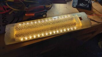
We might also want to add some extra lighting and a 12V compressor fridge; I definitely wanted to fit a battery monitor, so we could keep an eye on our power consumption while away from any hook-up.
Fitting the busbars and heavy battery cables now means less work for each future addition. Ours are rated at 150A and cost £18 for the pair.
Future-proofing
The scope of the project was pretty simple. We were going to run new battery cables to both positive and negative terminals. These would replace the thin cables already in place. The positive cable would run, via a main fuse, to a positive busbar. The negative cable could run directly to a negative busbar, but we wanted to install a modern battery monitor.
Typically, the battery indicator in a van tells you the voltage, which is not very helpful. If it tells you it has 12V, it’s flat. What you want to know is how long the lights are going to stay on and how much power is being drawn from the battery, so you can do something about it. For this, you need a battery monitor. Many of those need to connect directly to the negative terminal, with all circuits run through it to work.
Given this, we decided to fit the battery monitor at the same time as upgrading the cables.
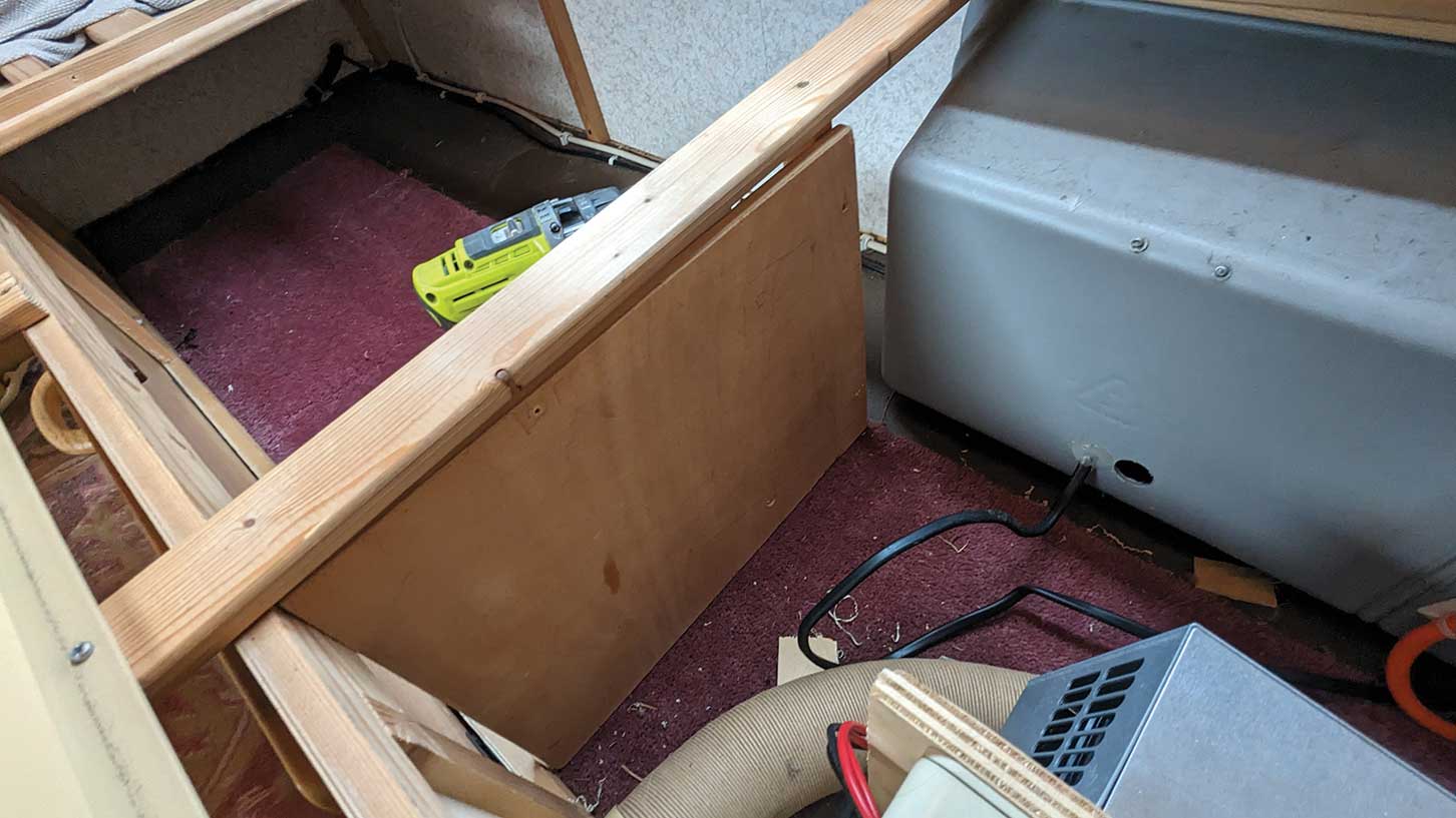
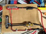
To keep the work simple, I decided to build up the circuits on the bench in my workshop, then mount the whole unit in one go. I found an offcut of 15mm plywood, which had formerly been part of our airing cupboard. With a bit of measuring, I was able to cut it to fit adjacent to the battery box, behind the mains consumer unit. This gave me good fixings into the seat base and easy access to all of the components I needed to get to. With the baseboard ready, I started planning how to logically lay out those components.
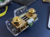
The battery monitor connects to a thing called a shunt. Once it’s fitted, you don’t really need to think about it again. I put the shunt for the battery monitor at the bottom, because this will not need to be accessed. I located the negative busbar next to it, to allow for easy connection.

The positive busbar was put at the top, to make adding extra circuits straightforward. This is connected directly to the battery via a surface-mounted 35A fuse. This was mounted at the top, to ensure it is accessible if trouble arises. We made sure each component had a logical cable run too, to avoid wasting expensive copper and to keep things neat.
The only other connections were a tiny cable, which was needed to provide power, and the main signal wire for the monitor display. The power cable was run to the positive busbar and clipped into place.
The circuits that we were creating were quite simple, but we were using heavy 110A flexible automotive cable, partly because I happened to have some in the workshop, but also because it was well up to the job. We needed strong, suitable connections.

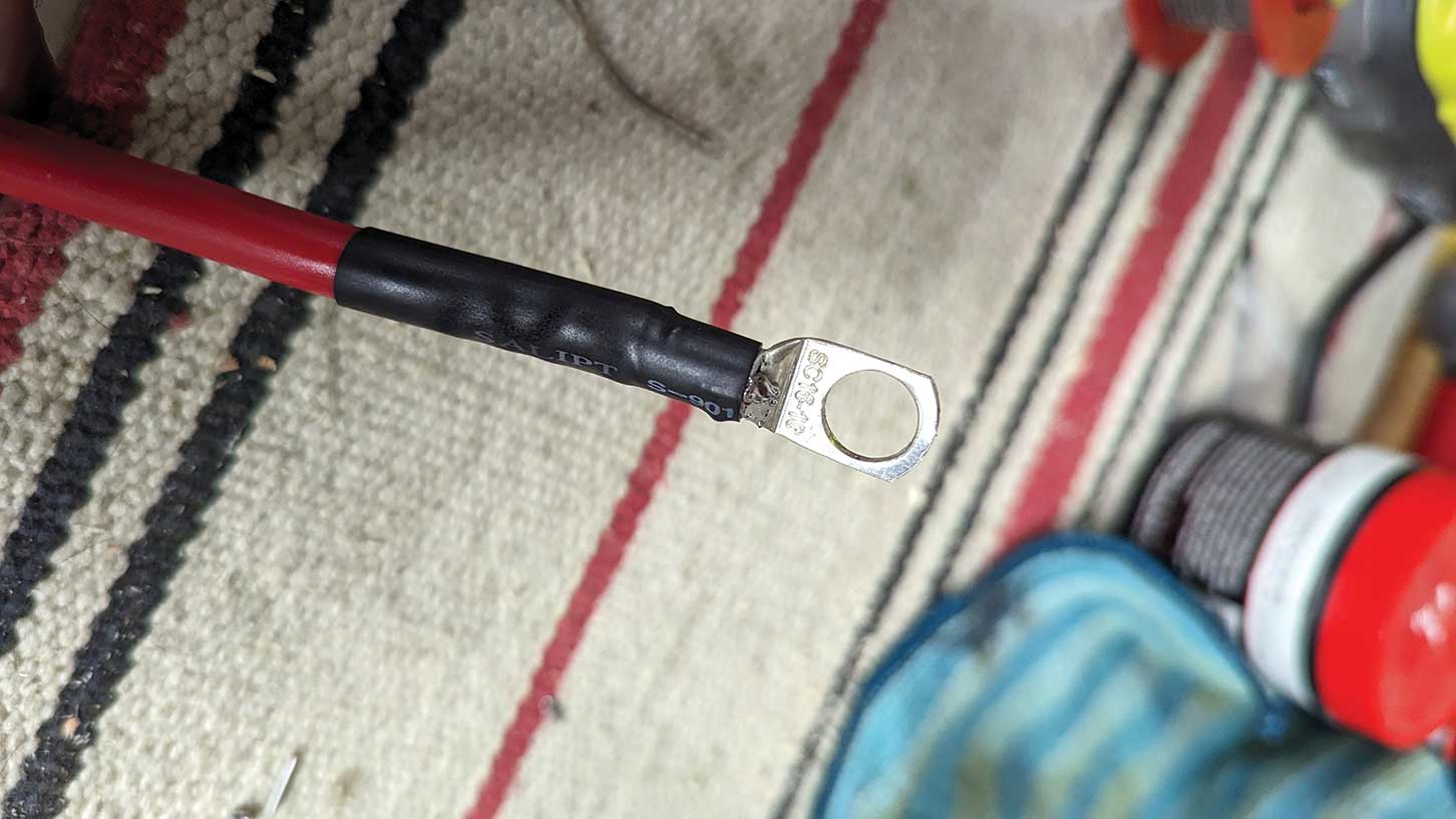
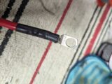
Although it might be a little old school, I opted to solder everything, tinning the new cables and terminals. Given the cable size, my old soldering iron was not really up to the job, so I went for a blowlamp instead.
It was a simple enough task, pushing the tinned cables into the terminals and heating up the terminals. There is a small hole in the solder terminals, into which I fed additional solder until it looked solid. The job was kept neat with some heatshrink tubing.
While making up your own cable runs might seem a bit of a headache, it ensures you can have the correct length and rating, and the right size terminal, for what you need.
For example, the battery monitor has 10mm terminals and the shunt, 6mm. I needed a cable run between them of around 200mm. That is not a cable you can buy off the shelf.
Wiring up
With the main cables, busbars and battery monitor shunt fitted, the final task was to adapt the existing wiring from the battery-charging system.

This was connected to the main van wiring loom with a moulded plug and was the only original connection from the battery to the rest of the caravan electrical system. I removed the original cable, shortened it, added new ring terminals to both positive and negative cables and attached them to the respective busbars. The cable run was kept neat with a couple of P-clips.
With all of the new cabling connected on the board, the whole piece was transplanted to the caravan to be installed. The new battery cables needed additional holes into the battery box. I had some 25mm gland fittings, so I drilled two 25mm holes for the new cables, fed them through and secured the glands to keep things neat.
Only the beginning
The final task was to bolt the battery cables to the terminals and power everything up.
Given what we currently have on the system, the 110A-rated cables attaching our battery to the new busbars are a bit ridiculous, but they are now future-proofed for anything we are likely to ask of them. And using cable found in the workshop saved a few quid.
Now, the only things attached to the busbars are the battery monitor and standard caravan mains charger. If we add solar panels, inverters, 12V sockets or other systems, we can simply run the cables from the charge controller to the busbars, rather than directly to the battery.
Future Publishing Limited, the publisher of Practical Caravan, provides the information in this article in good faith and makes no representation as to its completeness or accuracy. Individuals carrying out the instructions do so at their own risk and must exercise their independent judgement in determining the appropriateness of the advice to their circumstances and skill level. Individuals should take appropriate safety precautions and be aware of the risk of electrocution when dealing with electrical products. To the fullest extent permitted by law, neither Future nor its employees or agents shall have any liability in connection with the use of this information. You should check that any van warranty will not be affected before proceeding with DIY projects.
If you’ve enjoyed reading this article, why not get the latest news, reviews and features delivered direct to your door or inbox every month. Take advantage of our brilliant Practical Caravan magazine SUBSCRIBERS’ OFFER and SIGN UP TO OUR NEWSLETTER for regular weekly updates on all things caravan related.